Etiquetas

miércoles, 16 de septiembre de 2015

Loading a capacitor and visualization using Labview Data Acquisition

Loading a capacitor and visualization using Labview Data Acquisition


Data acquisition and signal acquisition consists in sampling the real world (analog system) to generate data that can be manipulated by a computer or other electronic (digital system). It consists in taking a set of physical signals, convert them into electrical voltages and digitize them so that they can be processed on a computer.
A stage of conditioning, which adapts the signal to levels compatible with the element that makes the transformation to digital signal is required. The element of this transformation is the scanning module or card Data Acquisition (DAQ).

The data acquisition process of the physical world involves the following key steps:

1. Using a sensor / transducer suitable for the variable you want
measuring, which can detect and convert the physical variable into an analog signal voltage or electric current.

2. Conditioning of the electrical signal: In this stage related problems are resolved obtained signal, such as noise, amplitude and / or signal strength, the nonlinearity of the same, among others.

3. Translation of the electrical signal to, own computer binary language: This process is technically known as analog / digital (A / D).

4. Storage of data in digital form, can be stored in the computer's memory and then displayed on the screen or in another peripheral thereof.

NI DAQ 6008


Our practice will be to acquire information that brings us load condenser and using Labview and DAQ thanks to visualize data in a chart with all that information. The DAQ that will use the National Instruments NI 6008.

The National Instruments USB-6008 is a low-cost, multifunction data acquisition device (DAQ). When one or more channels on each port is Set to Either input or output, the port is locked into That Particular mode.

The DAQ 6008 has the following characteristics:
• 8 analog inputs (12 bit, 10 kS / s)
• Static 2 analog outputs (12 bits); 12 E / digital S; 32-bit counter
• Powered by the bus for mobility, integrated signal connectivity
• The OEM version is available
• Compatible with LabVIEW, LabWindows ™ / CVI and Measurement Studio for Visual Studio .NET


NI 6008


NI 6008 inputs/outputs


Connection types


Another thing to keep in mind to develop this practice is that connection must be used to connect the signal source to the input corresponding card.

Generally there are three ways to apply signals to a data acquisition card:
- Differential mode
- RSE mode: referenced single-ended
- NRSE mode: single-ended nonreferenced

For this practice will use the RSE (referenced single-ended) mode and has the characteristic that all input signals are referenced to the common ground reference (GND) and the reference signal and the card they are the same.

The RSE type is the least recommended unless:
- The voltage level is high (> 1V)
- The cable length is short (> 30 cm) and are shielded
- Low noise environment
- The signals applied are all referring to ground (GND)


Calculations of the capacitor charge

These are the calculations we have done to find our capacitor and load time.

Value of capacitor chosen 455.1 micro farad
Tau = RC
2,175 K ohm resistor.
t = 5 RC
t = 5 x 2.175 x 455.1 = 4,949 seconds. This will be the loading time of our capacitor.


The transistor chosen is a BD 139


We designed a scheme capacitor discharge


Plate capacitor charge with Proteus


Then we will, by Proteus, a plaque on the need to place our capacitor also will place the transistor, relay and resistance to perform the charging of the capacitor.


Schematic capture of Proteus


Layout view


3D view


3D view


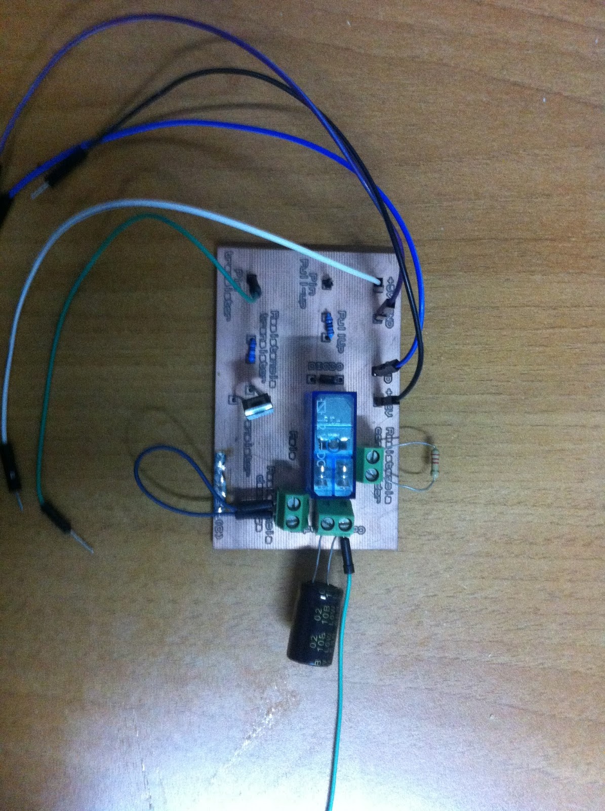
This is the result


Labview program


For this practice we perform a calculation for the load time of our condenser and then to test them with the program we will do in Labview.


A time made calculations proceed to make the calculations SubVI load
Condenser.


We proceed to make the freight SubVI
Condenser.


We proceed to perform the discharge SubVI
Condenser.


SubVI of time calculations


Now we proceed to implement the program using LabVIEW subVI previously created.


Explain briefly how the program works

Once the program started introduce the values ​​of either time or instant v and selecting the loading lever see the calculated values ​​and the graph will show us the loading ramp capacitor. The values ​​shown in the display and graphics coincide with our previous calculations.

Both voltage and the capacitance or resistance value will be measured with a precision of Fluke brand.

Make Arduino Board

Create an Arduino


This practice is to create an Arduino Uno board. We will design the plate based on the size of the original. The first thing we will do is take measures and design an original plate by Proteus. Once the plate with the location of its tracks and track changes designed'll take a copper plate and a CNC file will export our Proteus to manufacture the plate. Once we remacharemos plate track all changes and solder all the components needed to operate the plate.


Arduino Uno

Arduino is a free hardware platform based on a plate with a microcontroller and a development environment designed to facilitate the use of electronics in multidisciplinary projects.


Arduino Uno


The hardware consists of a plate with an Atmel AVR microcontroller and input / output. The most commonly used microcontrollers are the Atmega168, Atmega328, Atmega1280 and Atmega8 for its simplicity and low cost enable the development of multiple designs. On the other side is a software development environment that implements the language Processing / Wiring programming and the boot loader that is executed on the plate. The computer is programmed to control the board electronics.

The free integrated development environment can be downloaded free. Arduino can take information from the environment through their analog and digital inputs. It incorporates a reprogrammable microcontroller and a series of pin female inputs and outputs to connect easily and conveniently there different sensors so you can control lights, motors and other actuators. The Arduino microcontroller is programmed using the Arduino programming language (based on Wiring) and the Arduino development environment (based on Processing). The projects made with Arduino can run without connecting to a computer. It also has its own software that can be downloaded from their official website that already includes drivers of all available cards making easier loading codes from the computer.

The Arduino components are as follows


Bill Of Materials For
Design Title
Author
Document Number
Revision
Design Created
sábado, 04 de octubre de 2014
Design Last Modified
miércoles, 16 de septiembre de 2015
Total Parts In Design
59


0 Modules
Quantity
References
Value
Stock Code
Unit Cost
Sub-totals:
€0,00
12 Capacitors
Quantity
References
Value
Stock Code
Unit Cost
6
C1,­​C3-C4,­​C10-C12
100n
€0,23
1
C2
1uF
€0,09
2
C5-C6
22pf
€0,12
1
C7
1uf
€0,09
2
C8-C9
47u
€0,52
Sub-totals:
€2,84
16 Resistors
Quantity
References
Value
Stock Code
Unit Cost
1
R1
10k
RS461-3745
€0,21
2
R2,­​R10
1M
RS223-2653
€0,05
5
R3,­​R6-R7,­​R13,­​R16
560R
RS223-2221
€0,09
3
R4-R5,­​R8
1K
RS223-2265
€0,03
3
R9,­​R14-R15
10K
RS461-3745
€0,21
2
R11-R12
22R
RS740-9173
€0,10
Sub-totals:
€1,68
5 Integrated Circuits
Quantity
References
Value
Stock Code
Unit Cost
1
U1
ATMEGA328P
RS738-0435
€2,67
1
U2
ATMEGA16U2
RS715-3791
€3,30
1
U3
NCP1117ST50T3G
RS802-2130
€0,01
1
U4
LP2985-33DBVR
RS660-6733
€0,72
1
U5
LMV358MGKR
RS660-6727
€0,04
Sub-totals:
€6,74
1 Transistors
Quantity
References
Value
Stock Code
Unit Cost
1
Q1
FDN340P
RS671-0435
€0,04
Sub-totals:
€0,04
8 Diodes
Quantity
References
Value
Stock Code
Unit Cost
4
D1-D3,­​D7
LED-YELLOW
RS692-1102
€0,58
3
D4-D6
DIODE
RS773-4514
€0,03
1
D8
LED-VERDE
RS692-1102
€0,58
Sub-totals:
€2,99
17 Miscellaneous
Quantity
References
Value
Stock Code
Unit Cost
1
FU1
0.5A
RS647-8156
€0,37
1
J1
CONN-SIL10
RS797-3233
€1,26
1
J2
CONN-H6
RS765-5672
€1,09
2
J3-J4
CONN-H8
RS797-3239
€1,67
2
J5,­​J7
ICSP
RS681-2931
€0,35
1
J6
CONN-DIL4
€0,35
1
J8
CON_USB_B
RS748-0866
€1,21
1
J9
POWER JACK DC
RS 488-376
€0,40
1
JP1
JUMPER
RS745-7065
€0,07
1
L1
1u
RS724-1539
€0,01
1
S1
PULSADOR_DOBLE
RS378-6410
€0,32
2
VR1-VR2
VARISTOR CG0603MLC-05E
RS690-9938
€0,10
1
X1
RESONATOR
RS792-6524
€0,24
1
X2
CRYSTAL 16MHZ
RS226-1831
€1,33
Sub-totals:
€10,89

Totals:
€25,18


Photos arduinoooooo components

Two components stand out in our Arduino

ATMEGA 328P


The 8-bit AVR Atmega328 is an integrated high-performance RISC microcontroller is based circuit, combining 32KB ISP flash memory with the ability to read-while-write, 1KB of EEPROM memory, 2KB of SRAM, 23 lines I / S general purpose registers 32 overall process, three flexible timer / counters with comparison, internal and external interruptions, USART scheduler mode, byte-oriented serial interface 2 wire SPI serial port, 6- channel 10-bit A / D converter (8-chanales in TQFP and QFN / MLF packages), "watchdog timer" programmable internal oscillator and five modes software selectable saving energy. The device operates from 1.8 to 5.5 volts. By executing powerful instructions in a single clock cycle, the device achieves 1 MIPS response, balancing power consumption and processing speed.


ATMEGA 16U2


The high-performance, low-power 8-bit Atmel AVR RISC-based microcontroller combine With 16KB ISP flash memory read-while-write capabilities, 512B EEPROM, 512-Byte SRAM, 22 general purpose I / O lines, 32 general purpose working registers, two Flexible timer / counters With compare modes and PWM, USART, programmable watchdog timer With internal oscillator, SPI serial port, debugWIRE interface for on-chip debugging and programming, and five software selectable power saving modes. The device Operates betweeen 2.7-5.5 volts.
By executing powerful instructions in a single clock cycle, the device achieves throughputs approaching 1 MIPS per MHz, balancing power consumption and processing speed.


Proteus start our project in this scheme based on the Arduino Uno we found in internet


So we have the plate in Proteus


This is a genaral view of the plate in Proteus


This is the part of Atmega 16U2


This is the part of Atmega 328P


This is the part of the Jack


This is the part of connections


This is the part of Reset and ISCP


This is the part of Bypass


This is the part of USB


3D view


3D view


Layout view


We will export our board design to computer CNC


This is the CNC that we used


Once the plate on the CNC must be put rivets


Plate without rivets


Plate with rivets


Then we solder the components to the board


After soldering all the components on the board this is the end result, the board is ready.