Etiquetas

martes, 28 de abril de 2015

Artificial Vision 2 Checking for the Presence of a Part

This example introduces the Match Pattern, Measure Intensity, and SetCoordinate System steps.The instructions in this example are to create an inspection that checks for the presence of a spray bottle cap regardless of the bottle position in the inspection images.
Creating a New Inspection

Select File»New. Vision Builder AI opens a new, blank inspection.

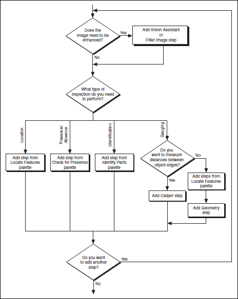
Acquiring Inspection Images

In the Inspection Steps palette, the Acquire Images tab contains several
acquisition steps you can use to acquire images from many different types
of cameras. The tab also contains a Simulate Acquisition step, which
simulates image acquisition by loading images from file. The Select Image
step enables you to switch to a previously acquired image that you need to
process later in the inspection.


Defining a Feature on which to Base aCoordinate System


In a machine vision inspection, you typically limit your inspection and processing to a region of interest (ROI) rather than the entire image for the following reasons:

• To improve your inspection results by avoiding extraneous objects
• To increase inspection speed

To limit the inspection area, the parts of the object you are interested in
must always be inside the ROI you define.
If the object under inspection is fixtured and always appears at the same
location and orientation in the images you need to process, defining an ROI
is straightforward. However, if the object under inspection appears shifted
or rotated within the images, the regions of interest need to shift and rotate
with the object under inspection.
For the regions of interest to move in relation to the object, you need to set
a coordinate system relative to a significant and original feature of the
object under inspection. Choose a feature that is always in the field of view
of the camera despite the different locations that the objects may appear in
from image to image. Also, make sure the feature is not affected by major
defects that could drastically modify the visual appearance of the feature.


Here we configure a Match Pattern step that
locates a bottle feature on which you can base a coordinate system.

1. In the Inspection Steps palette, select the Locate Features tab.
2. Click the Match Pattern step. The NI Vision Template Editor opens.
3. Draw a rectangle around the base of the sprayer, as shown in

The picture. This region becomes the pattern matching template.


4. Click Next.
5. Click Finish to accept the template.
6. On the Main tab, enter Locate Sprayer Base in the Step Name
control.
7. Redraw or decrease the default green ROI so that it surrounds only the
lower portion of the image, as shown in the picture.


8. On the Template tab, drag the red crosshair mark in the template
image to the left edge of the sprayer base, as shown in the picture. This
changes the focal point of the template.
9. The focal point indicates the part of the template that you want to
return as the match location. By default, the focal point is the center of
the template. You can modify the focal point by moving the red
crosshair or by specifying a Match Offset. Later in this inspection,
you use the match location as the origin of a coordinate system.


10. On the Settings tab, set Number of Matches to Find to 1.
11. On the Limits tab, enable the Minimum Number of Matches control,
and set the value to 1.
12. Click OK to add the step to the inspection.

Checking for the Cap Using Measure Intensity


The image of the spray bottle was acquired using a backlight. The cap
appears dark on the bright background. Complete the following
instructions to configure a Measure Intensity step to check for the
presence of a spray bottle cap.

1. In the Inspection Steps palette, select the Check for Presence tab.

2. Click the Measure Intensity step. The property page for the step
opens.

3. On the Main tab, enter Check Cap Presence in the Step Name
control.

4. Enable the Reposition Region of Interest control.
Enabling this control allows you to link the regions of interest specified
in this step to a previously defined coordinate system so that
Vision Builder AI can adjust the location and orientation of the ROI
from image to image relative to the specified coordinate system.

The Reference Coordinate System list shows all the previously
defined coordinate systems. Coordinate System is the default
reference coordinate system because it is the only Set Coordinate
System step in the current inspection.

Notice that the Measure Intensity step supports a variety of different tools
that enable you to draw different shaped regions of interest, such as a point,
line, broken line, freehand line, rectangle, ellipse, annulus, polygon, and
freehand region. These tools are available in the main menu bar.
5. Using the default Rectangle Tool, hold down the <Ctrl> key, and draw
three regions of interest that enclose edges of the cap, as shown in
the picture. Pressing the <Ctrl> key enables you to draw multiple
regions of interest for the step.


6. Click the Limits tab.
At the bottom of the tabbed page, Vision Builder AI returns the
intensity statistics of the pixels inside the regions of interest. Pixel
intensities can range from 0–255, where 0 equals black and 255 equals
white.
The Minimum Intensity value at the bottom of the page returns the
lowest pixel value inside the regions of interest. The backlit edges of
the plastic cap appear in silhouette as dark pixels (which have low pixel
intensities) on a bright background (which has high pixel intensities).

Therefore, when the cap is present, the minimum intensity for the
regions is low. When the cap is not present, the minimum intensity for
the regions is high because the regions contain only bright background
pixels.

7. Enable the Minimum Intensity control. Set the Maximum value
to 50.00.
8. Click OK to add the step to the inspection.
9. Click the Run State Once button located in the State Configuration
window.

Artificial Vision 1 Introduction to Vision Builder

About Vision Builder


The Vision Builder program is designed to be an adjunct tool used as part of a comprehensive optometric vision therapy program. Your optometrist will give you guidance as to which parts of the program are best suited to your specific needs and as such should be the one to tell you what levels and settings would be best for you and the continued development of your visual abilities.

You may use Vision Builder as a stand-alone tool to improve your visual abilities, but the use of any computer program will never replace the need for a comprehensive vision therapy program.
The program has been tested on the operating systems Windows XPWindows VistaWindows 7 and Windows 8


Vision Builder AI has two modes of operation: Configuration and
Inspection. Use the Configuration interface to configure and test your
inspection. Use the Inspection interface to deploy the software and perform
online or offline visual inspection.


Elements of the Configuration Interface


Here shows the Vision Builder AI Configuration interface. The
Configuration interface contains four areas: Main window, Overview
window, Inspection Steps palette, and State Configuration window.


Main window 
Displays the image in which you are working, which may be the state diagram or the property page where inspection arrangements are made, regions of interest are defined in the image and the parameters of the steps are configured to perform .

Overview window Displays a thumbnail of any current
image inspection or the state diagram for inspection.

Inspection Steps palette
Lists and describes the steps that you use
to create your inspection. When you click on most steps, the palette
transforms into the property page for the step.

State Configuration window
Displays the list of steps in the
currently selected state in the inspection.

Inspection State Diagram
The program uses a state diagram to define the inspections setting states and transitions leading program execution.
You can do simple inspection of a single state.


More complex inspections can be created by adding additional states and transitions to the default state diagram.


Within a state diagram, each state can lead to one or multiple states or can end the inspection cycle.

Each state diagram relies on in-state calculations or user input to determine the next state to execute. 

The program executes the state diagram continuously from the start point to the end point.
Each state in an inspection is intended to contain a discrete set of inspection steps.


To access the steps contained in a state, select the state on the state diagram. The steps present in the state will appear in the State Configuration window.

Vision Builder AI Inspection Interface


Results Panel 
Lists the steps in the inspection by name. For each
inspection step, Vision Builder displays the step type, result (PASS or
FAIL), measurement made, and a comment explaining the reason of a
FAIL. Inspection Status shows the result of the complete inspection.

Display window 
Displays the part under inspection.


Inspection Statistics panel 

Contains three indicators that display

the yield (ratio between PASS and FAIL), active versus idle time, and

processing time of the inspection.

miércoles, 22 de abril de 2015

Unipolar Stepper Motor

Introduction


The stepper motor is an electromechanical device that converts electrical pulses into angular displacement. It is CapAd forward a series of steps (degrees) depending on the value of their tickets.
There are two types unipolar and bipolar; in our case study first.
The microcontroller system we use is the arduino, an easy way to control these motors.

Experimental Material


 - Arduino Uno


Driver unipolar motors


- Unipolar motor


Structure


The stepper motor consists of a rotor and a stator. In the rotor are certain numbers of magnets, while the stator coils are located.


Figure 1. Structure of unipolar motor.

Wiring


Usually has 5 output cables, which are: four for the coils and one for the common (in certain engines can be 2 wires and not be attached). To use an encapsulated diode is needed, in our example ULN2803 (8 diode array) is used.


Coils normally come determined by A, B, C and D.


Figure 2. Connecting the unipolar motor with ULN2803.


Performance


For the engine to run, it must be properly polarize the coils and in the right order, so that the magnet is moved to one side or the other. If the sequence used is not correct, the engine may have awkward movements skipping any steps (degree) turn in the desired direction, or is not moving and just vibrate.
If the sequence used is correct, the motor will run perfectly, the only problem you may encounter is the frequency of rotation, because if we use too fast the engine will be unable to move or skip some steps.
There are three ways to polarize the coil:

Step by step polarizing two coils: This is the most used, since two coils activating the motor torque is large. In this case the motor will move from step to step, so you will need 4 steps to turn around.


Figure 3. Sequence for operation step by step activating two coils.

In our case, the internal engine needs to perform 8 times this sequence, so you need 4x8 = 32 steps for a spin.
It also has a reducer 64 so to give back to the outer shaft should be given 32x64 = 2048 steps.

Step Medium: in this case, two coils are applied first, then one and so on, so that steps twice that in the case above is performed. This sequence is used when we need more accuracy in the rotation, because to make a turn employ 8/2 steps instead of 4 steps.

  At times the torque is lower than in the previous case, but the accuracy is compensated.


Figure 4. Sequence for operation at half steps.

As in the previous case, our engine must perform this sequence 8 times to perform a rotation of the internal engine, so that 8x8 = 64 steps perform media.

The outer engine must perform 64 times this sequence because too reductive, so the outer shaft should give 64x64 = 4096/2 steps for a spin.

Footsteps activating a coil: this sequence is the least used because the torque is small to activate only one coil, and the number of steps is equal to the first example, so you do not gain in precision and lose torque.

Because of this we have not tested this sequence.

Comments


To make a change in the engine rotational just have to make the sequence in reverse.

The speed is increased step by step making a half steps. This can be seen in the videos.

If you do not have the motor data and know no coils, can be identified as follows:

If you do not have the motor data, and we know that each coil wire is for then is explained a way to identify each coil and common.

Select a cable and connect to ground. That will be called Cable A.


A cable holding grounded, test which of the remaining three wires cause a step counter being also connected to ground sense.

 That will be the cable B.


A cable holding grounded, test which of the two remaining wires clockwise causes a step to be grounded sense. That will be the cable D.


The last cable should be the cable C. To check, simply connect to ground, which should not cause any movement because it is the opposite coil to the A.

The name of each coil has been set arbitrarily, and may be designated in any manner.


martes, 21 de abril de 2015

Bipolar Stepper Motors

Introduction


Bipolar motors will try are a type of stepper motors. Before explaining how they work and what features have bipolar stepper motors will explain some basic questions.
The stepper motors can be seen as brushless electric motors. Typically all motor windings are part of the stator and the rotor can be a permanent magnet or, in the case of variable reluctance motors (which best describe later), a solid cylinder shaped machining teeth ( like a gear), built with materials magnetically "soft" (such as soft iron).
The stepper motors are ideal for building mechanisms where very precise movements are required.
The main feature of these engines is being able to move one step at a time for each pulse that is applied. This step may vary from 90 ° to small movements of only 1.8 °, ie that four steps are needed in the first case (90 °) and 200 for the second case (1.8 °), to complete a full 360 °.
These motors have the ability to be locked in position or completely free. If one or more of its coils are energized, the motor is set in the corresponding position and instead be completely free if no current flows through any of its coils.
The switch must be handled externally with an electronic controller and typically motors and controllers are designed so that the engine can be kept in a fixed position and so that it can be rotated in one direction and in the another.
Most step-known stepper motors can be advanced audio frequencies, allowing them to spin very fast. With a suitable driver, you can make them start and stop instantly in controlled positions.

Own behavior stepper motors


The stepper motors have a completely different behavior of DC motors. First, do not rotate freely for themselves. The stepper motors, as the name implies, turning advance by small steps. They also differ from DC motors in the relationship between speed and torque (a parameter which is also called "torque" and "torque"). DC motors are not good to provide a good low speed torque without the help of a reduction mechanism. The step, however, engines work the opposite way: its greater torque occurs at low speed.

The stepper motors have an additional feature: the torque of detention (which can be seen also referred to as "cogging torque" and even par / torque "maintenance"), which does not exist in DC motors. The torque detention makes a stepper motor is held firmly in position when not rotating. This feature is useful when the motor stops moving and while stopped, the loading force remains applied to its axis. This eliminates the need for a brake mechanism.

While the stepper motors operate controlled by a pulse of progress, controlling a stepper motor is not performed live using this electrical pulse that feeds it. These engines have several windings, to produce the advancement of that step, should be fed in a proper sequence. If the order of the sequence is reversed, it is achieved that the motor rotates in the opposite direction. If power pulses are not provided in the correct order, the motor will not move properly. It may be that buzz and do not move, or you may turn, but in a rough and irregular.


This means turning a stepper motor is not as simple as doing a DC motor, which is given a power and ready. A control circuit, which is responsible for converting signals forward a step and direction of rotation in the required sequence of energizing the windings is required.

Common characteristics of stepper motors


A stepper motor is defined by these basic parameters:

Voltage


The stepper motors have an electrical voltage. This value is printed on its casing or at least specified in the datasheet. Sometimes it may be necessary to apply a higher voltage to achieve a given engine meets the desired torque, but this produce overheating and / or shorten engine life.
Electrical resistance

Another characteristic of a stepper motor is the resistance of the windings. This resistance will determine the current engine consumes, and its value affects the torque curve of the engine and its maximum operating speed.
Degrees per step

Generally, this is the most important when choosing a stepper engine for a particular use factor. This factor defines the number of degrees rotate the axis for each full step. A half-step operation or semi-step (half step) motor double the number of steps per revolution to reduce the number of degrees per step. When the value of degrees per step is not shown on the motor, it is possible to have on hand the number of steps per revolution, cranking and feeling by touch each "tooth" magnetic. The degrees per step are calculated by dividing 360 (a full turn) by the number of steps counted. The most common quantities of degrees per step is 0.72 °, 1.8 °, 3.6 °, 7.5 °, 15 ° and 90 °. This value of degrees per step usually is called the resolution of the motor. In the event that an engine does not indicate the degrees per step in his case, but the number of steps per revolution, dividing that value by 360 the number of degrees per step is obtained. An engine of 200 steps per revolution, for example, have a resolution of 1.8 ° per step.
Bipolar stepper motors

Bipolar motors and control circuits require more complex power. But today this is no problem, since these circuits are usually implemented in an integrated, that solves this complexity into a single component. How much should add some power components such as transistors and diodes for the crosscurrents, although this is not necessary in small and medium motors.

Since there are twice winding unipolar (remember that these all the time you are using only one of the duplicate coil, while the other is disabled and useless), bipolar motors offer a better relationship between torque and size / weight.


Distribution of a bipolar motor winding


Bipolar configuration engines requires that the coils receive power in either direction, not only on-off as unipolar. This necessitates the use of an H bridge (a circuit composed of at least six transistors) on each of the windings.


Pulse sequence for a bipolar motor


The following is an example circuit for handling one of the coils (one like you need to handle a full motor).


Drive circuit for a bipolar motor


Sequence to control bipolar stepper motors


A bipolar stepper motor needs reversing the current in its coils in a certain sequence to cause movement of the shaft.


Step
Coil 1A
Coil 1B
Coil 2A
Coil 2B
Step 1
1
0
1
0
Step 2
1
0
0
1
Step 3
0
1
0
1
Step 4
0
1
1
0

Sequence to control Middle Bipolar stepper motors (Half step)


You can also program the stepper motor to advance media, meaning greater precision. With this mode of operation, the rotor moves half step for each excitation pulse, presenting the main advantage further step resolution, decreasing the angular advance (half in full step mode). To achieve such purpose, the excitation mode it is alternately on two coils and one of them, as shown in Table 2 for both directions


Step
Coil 1A
Coil 1B
Coil 2A
Coil 2B
Step 1
1
0
0
0
Step 2
1
1
0
0
Step 3
0
1
0
0
Step 4
0
1
1
0
Step 5
0
0
1
0
Step 6
0
0
1
1
Step 7
0
0
0
1
Step 8
1
0
0
1


Identify a bipolar motor


In the case of motors bipolar stepper (usually 4 output cables), identification is simple. Simply taking a tester in ohmmeter mode (to measure resistance), we can find the cable pairs corresponding to each coil, because between them must be continuity (actually a very low resistance). Then we find only the same polarity, which is easily obtained by testing. That is, if connected in one way does not work, just give back the wires of a coil and then it should work fine. If the direction of rotation is opposite to expectations, simply invert the connections of both coils and the H-Bridge.

Method for operating our bipolar stepper


Materials


- One Arduino micro controller -Placa Rev3.0


- Controller Card engines Microbot MR007-001.1


- Motor Bipolar Portescap 15M020D1E
- Two cables Arduino
- USB Cable & Charger for Arduino


First we must properly report on the material we are using to configure it without causing any harm to self or our computer's USB controller.

Our engine controller is preset entries which we are using in the Arduino to operate the motor. Also according to their datasheet see what we can do the reading of other sensors with the same system that does not employ this time.

As can be seen in the tables, we have two control channels for the engine and each has a channel activation.

Table datasheet.


Channel 1: Pines 9 and 10 of our Arduino and pin 3 activation
Channel 2: Pins 2 and 6 of our Arduino and pin 5 activation
These are the pins to continually set to crank the engine, but first we must see the features of it with the following table.


The most important features of our engine must emphasize that consumes 200mA with both coils working, the operating voltage is 5 volts and needs to give 20 steps to make a full turn, so accuracy is 18 degrees whole steps. Finally will be shown on image to belong coil cables and coding operation.


But we had it with a multimeter would look which belongs to each coil.


Once known all necessary data in our material, we see the same Arduino can feed the bipolar motor because it does not exceed the capacity of the same, so we will connect the motor windings one on each channel, connect power channels and connect to our Arduino controller.


Once connected everything will open a Arduino Sketch and start to make our program.


Declaration of variables


Declare the variables that we will use.

// Declare the pins of the coils and subsequently enable


  #define motorPin1 9
  #define motorPin2 10
  #define motorPin3 2
  #define motorPin4 6
  #define EnA 3
  #define EnB 5


// Variable that specifies the time between steps and a variable // employ more forward and will reset function

 int i=500;
 int a=0;

Pinout


We configure the pin as an output to the controller detects engine and initialize serial communications.

void setup()
 {

 // We set the pins specified in the datasheet as outputs

 pinMode(motorPin1, OUTPUT);
 pinMode(motorPin2, OUTPUT);
 pinMode(motorPin3, OUTPUT);
 pinMode(motorPin4, OUTPUT);
 pinMode(EnA, OUTPUT);
 pinMode(EnB, OUTPUT);

 // Initialize serial communication

 Serial.begin(9600);


 Setting the sequence engine


Now configure the sequence of the engine, which already have defined at the beginning of this practice. As we can see the end it gets a clasp to close your starting with the setup.

// We perform a function that is repeated as many times as you need to give a complete turn

  // In our case it is an engine of 20 steps per revolution so that the sequence will repeat 5 times.


    for(a=0;a<5;a++)
    {
      delay(i);     
      digitalWrite(9,1);
      digitalWrite(10,0);
      digitalWrite(2,1);
      digitalWrite(6,0);
      digitalWrite(3,1);
      digitalWrite(5,1);
     
      delay(i);
      digitalWrite(9,0);
      digitalWrite(10,1);
      digitalWrite(2,1);
      digitalWrite(6,0);
      digitalWrite(3,1);
      digitalWrite(5,1);
 
      
      delay(i);
      digitalWrite(9,0);
      digitalWrite(10,1);
      digitalWrite(2,0);
      digitalWrite(6,1);
      digitalWrite(3,1);
      digitalWrite(5,1);

      delay(i);
      digitalWrite(9,1);
      digitalWrite(10,0);
      digitalWrite(2,0);
      digitalWrite(6,1);
      digitalWrite(3,1);
      digitalWrite(5,1);
            
      }

 }

As we can observe the movement of the engine is a synchronism between a coil and another with 4 steps, which repeat 5 times and give us a full turn our engine, because its rotor has 20 polarizations.