Introduction
Bipolar motors will try are a type of stepper motors. Before explaining how they work and what features have bipolar stepper motors will explain some basic questions.
The stepper motors can be seen as brushless electric motors. Typically all motor windings are part of the stator and the rotor can be a permanent magnet or, in the case of variable reluctance motors (which best describe later), a solid cylinder shaped machining teeth ( like a gear), built with materials magnetically "soft" (such as soft iron).
The stepper motors are ideal for building mechanisms where very precise movements are required.
The main feature of these engines is being able to move one step at a time for each pulse that is applied. This step may vary from 90 ° to small movements of only 1.8 °, ie that four steps are needed in the first case (90 °) and 200 for the second case (1.8 °), to complete a full 360 °.
These motors have the ability to be locked in position or completely free. If one or more of its coils are energized, the motor is set in the corresponding position and instead be completely free if no current flows through any of its coils.
The switch must be handled externally with an electronic controller and typically motors and controllers are designed so that the engine can be kept in a fixed position and so that it can be rotated in one direction and in the another.
Most step-known stepper motors can be advanced audio frequencies, allowing them to spin very fast. With a suitable driver, you can make them start and stop instantly in controlled positions.
Own behavior stepper motors
The stepper motors have a completely different behavior of DC motors. First, do not rotate freely for themselves. The stepper motors, as the name implies, turning advance by small steps. They also differ from DC motors in the relationship between speed and torque (a parameter which is also called "torque" and "torque"). DC motors are not good to provide a good low speed torque without the help of a reduction mechanism. The step, however, engines work the opposite way: its greater torque occurs at low speed.
The stepper motors have an additional feature: the torque of detention (which can be seen also referred to as "cogging torque" and even par / torque "maintenance"), which does not exist in DC motors. The torque detention makes a stepper motor is held firmly in position when not rotating. This feature is useful when the motor stops moving and while stopped, the loading force remains applied to its axis. This eliminates the need for a brake mechanism.
While the stepper motors operate controlled by a pulse of progress, controlling a stepper motor is not performed live using this electrical pulse that feeds it. These engines have several windings, to produce the advancement of that step, should be fed in a proper sequence. If the order of the sequence is reversed, it is achieved that the motor rotates in the opposite direction. If power pulses are not provided in the correct order, the motor will not move properly. It may be that buzz and do not move, or you may turn, but in a rough and irregular.

This means turning a stepper motor is not as simple as doing a DC motor, which is given a power and ready. A control circuit, which is responsible for converting signals forward a step and direction of rotation in the required sequence of energizing the windings is required.
Common characteristics of stepper motors
A stepper motor is defined by these basic parameters:
Voltage
Electrical resistance
Another characteristic of a stepper motor is the resistance of the windings. This resistance will determine the current engine consumes, and its value affects the torque curve of the engine and its maximum operating speed.
Degrees per step
Generally, this is the most important when choosing a stepper engine for a particular use factor. This factor defines the number of degrees rotate the axis for each full step. A half-step operation or semi-step (half step) motor double the number of steps per revolution to reduce the number of degrees per step. When the value of degrees per step is not shown on the motor, it is possible to have on hand the number of steps per revolution, cranking and feeling by touch each "tooth" magnetic. The degrees per step are calculated by dividing 360 (a full turn) by the number of steps counted. The most common quantities of degrees per step is 0.72 °, 1.8 °, 3.6 °, 7.5 °, 15 ° and 90 °. This value of degrees per step usually is called the resolution of the motor. In the event that an engine does not indicate the degrees per step in his case, but the number of steps per revolution, dividing that value by 360 the number of degrees per step is obtained. An engine of 200 steps per revolution, for example, have a resolution of 1.8 ° per step.
Bipolar stepper motors
Bipolar motors and control circuits require more complex power. But today this is no problem, since these circuits are usually implemented in an integrated, that solves this complexity into a single component. How much should add some power components such as transistors and diodes for the crosscurrents, although this is not necessary in small and medium motors.
Since there are twice winding unipolar (remember that these all the time you are using only one of the duplicate coil, while the other is disabled and useless), bipolar motors offer a better relationship between torque and size / weight.

Distribution of a bipolar motor winding
Bipolar configuration engines requires that the coils receive power in either direction, not only on-off as unipolar. This necessitates the use of an H bridge (a circuit composed of at least six transistors) on each of the windings.

Pulse sequence for a bipolar motor
The following is an example circuit for handling one of the coils (one like you need to handle a full motor).

Drive circuit for a bipolar motor
Sequence to control bipolar stepper motors
A bipolar stepper motor needs reversing the current in its coils in a certain sequence to cause movement of the shaft.

Step
|
Coil 1A
|
Coil 1B
|
Coil 2A
|
Coil 2B
|
Step 1
|
1
|
0
|
1
|
0
|
Step 2
|
1
|
0
|
0
|
1
|
Step 3
|
0
|
1
|
0
|
1
|
Step 4
|
0
|
1
|
1
|
0
|
Sequence to control Middle Bipolar stepper motors (Half step)
You can also program the stepper motor to advance media, meaning greater precision. With this mode of operation, the rotor moves half step for each excitation pulse, presenting the main advantage further step resolution, decreasing the angular advance (half in full step mode). To achieve such purpose, the excitation mode it is alternately on two coils and one of them, as shown in Table 2 for both directions
Step
|
Coil 1A
|
Coil 1B
|
Coil 2A
|
Coil 2B
|
Step 1
|
1
|
0
|
0
|
0
|
Step 2
|
1
|
1
|
0
|
0
|
Step 3
|
0
|
1
|
0
|
0
|
Step 4
|
0
|
1
|
1
|
0
|
Step 5
|
0
|
0
|
1
|
0
|
Step 6
|
0
|
0
|
1
|
1
|
Step 7
|
0
|
0
|
0
|
1
|
Step 8
|
1
|
0
|
0
|
1
|
Identify a bipolar motor
In the case of motors bipolar stepper (usually 4 output cables), identification is simple. Simply taking a tester in ohmmeter mode (to measure resistance), we can find the cable pairs corresponding to each coil, because between them must be continuity (actually a very low resistance). Then we find only the same polarity, which is easily obtained by testing. That is, if connected in one way does not work, just give back the wires of a coil and then it should work fine. If the direction of rotation is opposite to expectations, simply invert the connections of both coils and the H-Bridge.
Method for operating our bipolar stepper
Materials
- One Arduino micro controller -Placa Rev3.0

- Controller Card engines Microbot MR007-001.1


- Motor Bipolar Portescap 15M020D1E
- Two cables Arduino
- USB Cable & Charger for Arduino
First we must properly report on the material we are using to configure it without causing any harm to self or our computer's USB controller.
Our engine controller is preset entries which we are using in the Arduino to operate the motor. Also according to their datasheet see what we can do the reading of other sensors with the same system that does not employ this time.
As can be seen in the tables, we have two control channels for the engine and each has a channel activation.
Table datasheet.

Channel 1: Pines 9 and 10 of our Arduino and pin 3 activation
Channel 2: Pins 2 and 6 of our Arduino and pin 5 activation
These are the pins to continually set to crank the engine, but first we must see the features of it with the following table.
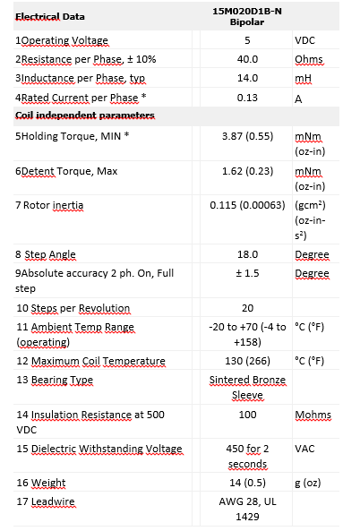
The most important features of our engine must emphasize that consumes 200mA with both coils working, the operating voltage is 5 volts and needs to give 20 steps to make a full turn, so accuracy is 18 degrees whole steps. Finally will be shown on image to belong coil cables and coding operation.
But we had it with a multimeter would look which belongs to each coil.

Once known all necessary data in our material, we see the same Arduino can feed the bipolar motor because it does not exceed the capacity of the same, so we will connect the motor windings one on each channel, connect power channels and connect to our Arduino controller.

Once connected everything will open a Arduino Sketch and start to make our program.
Declaration of variables
Declare the variables that we will use.
// Declare the pins of the coils and subsequently enable
#define motorPin1 9
#define motorPin2 10
#define motorPin3 2
#define motorPin4 6
#define EnA 3
#define EnB 5
int i=500;
int a=0;
Pinout
We configure the pin as an output to the controller detects engine and initialize serial communications.
void setup()
{
pinMode(motorPin1, OUTPUT);
pinMode(motorPin2, OUTPUT);
pinMode(motorPin3, OUTPUT);
pinMode(motorPin4, OUTPUT);
pinMode(EnA, OUTPUT);
pinMode(EnB, OUTPUT);
// Initialize serial communication
Serial.begin(9600);
Setting the sequence engine
// We perform a function that is repeated as many times as you need to give a complete turn
// In our case it is an engine of 20 steps per revolution so that the sequence will repeat 5 times.
for(a=0;a<5;a++)
{
delay(i);
digitalWrite(9,1);
digitalWrite(10,0);
digitalWrite(2,1);
digitalWrite(6,0);
digitalWrite(3,1);
digitalWrite(5,1);
delay(i);
digitalWrite(9,0);
digitalWrite(10,1);
digitalWrite(2,1);
digitalWrite(6,0);
digitalWrite(3,1);
digitalWrite(5,1);
delay(i);
digitalWrite(9,0);
digitalWrite(10,1);
digitalWrite(2,0);
digitalWrite(6,1);
digitalWrite(3,1);
digitalWrite(5,1);
delay(i);
digitalWrite(9,1);
digitalWrite(10,0);
digitalWrite(2,0);
digitalWrite(6,1);
digitalWrite(3,1);
digitalWrite(5,1);
}
}
As we can observe the movement of the engine is a synchronism between a coil and another with 4 steps, which repeat 5 times and give us a full turn our engine, because its rotor has 20 polarizations.
No hay comentarios:
Publicar un comentario